Saturday, December 24, 2022

Thermal Power Plant: Types of Coal, Layout, and Working Principle

Generation of Thermal Power:

About 58% (2,36,018 MW) of  India's electricity capacity comes from thermal power stations, and 88%(210,600 MW) of that energy is generated by coal-based thermal power plants. Other sources (that generate high-temperature steam) include crude oil, liquid natural gas, and biomass.
There are four different types of coal found in India which are Anthracite(85-92% C), Bituminous(76-86% C), Lignite(60-70% C), and Peat. Peat is not used in thermal power generation because it has only 30 to 40% carbon, but the other three varieties are used widely. Of the above four types, bituminous coal is found in the maximum amounts in India.
Thermal Power Plant Layout

Working Principle:

In a thermal power plant, heat energy is converted into electricity. It is based on the Rankine cycle. In a thermal power plant, heat is produced by burning coal. Steam is generated by this heat in the boiler, which turns the turbine. A synchronous generator is connected to the shaft of the turbine. The turbine provides the mechanical energy input to the generator, which is converted into electricity by the electro-mechanical energy conversion process.

Application of Different Blocks:

Low-Pressure and High-Pressure heaters:

Low Pressure and High-Pressure heaters are steam heaters. They are used for increasing the water temperature for improvement of efficiency. Steam is used to heat the condensate water from the condenser in the low-pressure heater, which is extracted from low-pressure turbines. The water after Boiler Feed Pump gets heated by an HP heater by steam which is extracted from High Pressure & Inter-Pressure turbines.

Deaerator:

The pressure exerted by certain gases (Oxygen, carbon dioxide, and ammonia) dissolved in water is harmful because of their corrosive behavior towards metals, particularly at elevated temperatures. Thus in the modern high-pressure boiler (for preventing internal corrosion), the feed water should be free from all dissolved gases, especially oxygen. This job is done by the deaerator that removes dissolved gasses to protect turbine blades.

Economizer:

Economizer extracts the heat from the flue gases and uses it to raise the boiler feed water's temperature to increase the system's efficiency. In simple words, An economizer is employed to absorb heat from the fired coal to improve efficiency.

Boiler-Feed Pump:

Boiler-Feed Pump is the highest-pressure generating pump in a thermal power plant. It consumes around 4MW of power. Water circulates naturally from the drum to the boiler and again to the drum due to the density difference between the water and the steam. In high-capacity generators (more than 200MVA) extra pump is used for this purpose.

Turbo Separator:

A turbo separator is used for separating water and steam inside the drum.

High-Temperature Super Heater:

HTSH is used for heating the steam temperature up to 540℃.

Inter-Temperature Super Heater:

ITSH is used for re-heating the steam to improve efficiency. As per the Rankine cycle, steam is directly sent from Inter Pressure Turbine to Low-Pressure Turbine.

Cooling Tower:

Steam is Condensed using circulating water which is cooled by in cooling tower. The exhaust steam from the turbine transfers the heat to the cooling water. This steam cannot be converted to work and must be rejected to restore the initial condition of the working fluid. The condenser enables the exhaust steam to be used as the working fluid of the boiler in repetitive mode. A vacuum is created inside the condenser that increases the turbine's output. Almost 50% of energy is wasted inside the condenser in converting steam into water.

Primary Air Fan:

PA fans are high-pressure fans used for conveying coal powder from the mill to the boiler.

Forced Draft Fan:

Oxygen is supplied by the FD fan to the boiler for proper combustion.

Induced Draft Fan:

ID fan is used to extract flue gasses from the boiler.

Electrostatic Precipitator:

ESP is used to collect ash particles from the flue gases that work on the principle of the electrical field.

Air Pre Heater:

APH is used for removing moisture from the coal.

High-Pressure Governor Control Valve:

HPCV and IPCV are the governing control valves, controlling the turbine's steam flow rate so that speed, frequency, and load are regulated.

In thermal power plants, 8-10% of the power generated is used for auxiliary equipment. Therefore the efficiency of thermal power plants is around 35-40%.

Wednesday, December 21, 2022

Bagasse & Cogeneration of Renewable Energy

What is Bagasse? How is it used as a Renewable Energy source?

Bagasse is the fibrous matter that remains after sugarcane or sorghum stalks are crushed to extract their juice. It is a by-product generated in the process of manufacturing sugar. It can either be sold or be captively consumed for generation of steam. It is currently used as a biofuel and manufacturing of pulp and paper products and building materials. The bagasse produced in a sugar factory is used for generating steam. This steam is used as a fuel source. The surplus generation is exported to the power grids of state governments.

Sugarcane Bagasse
Sugarcane Bagasse

According to the Indian Sugar Mills Association(ISMA), as of 31st January 2022, 507 sugar mills in the country were in operation and had produced 187.08 lac tons of sugar, as compared to 177.06 lac tons produced by 491 mills last season which operated on the corresponding date. This is 10.02 lac tons higher as compared to the last season’s production for the corresponding period.
India emerges as the world’s largest producer and consumer of sugar and the world’s 2nd largest exporter of sugar, records over 5000 LMT of sugarcane produced in sugar season 2021-22; 35 LMT of sugar used for ethanol production and 359 LMT sugar produced by sugar mills in the season, and records the highest sugar exports of 109.8 LMT.

What is Cogeneration?

When two forms of energy (where one must always be heat and the other can either be mechanical or electrical) are produced from one fuel, it is called Cogeneration. In a cogeneration plant, very high-efficiency levels can be reached in the range of 75%–90%. This is so because the low-pressure exhaust steam coming from the turbine is not condensed but used for heating purposes in factories or houses.

The Technology of Electricity Generation & Transmission:

The prime technology for sugar mill cogeneration is the conventional steam-Rankine cycle design for converting fuel into electricity. A combination of stored and fresh bagasse is usually fed to a specially designed furnace to generate steam in a boiler at typical pressures and temperatures of usually more than 40 bars and 440°C respectively. The high-pressure steam is then expanded either in back pressure or single extraction back pressure or single extraction condensing or double extraction cum condensing type turbo generator operating at similar inlet steam conditions.
Co-generation Plant
Rankine Cycle

Bagasse (when burned in quantity) produces sufficient heat energy to supply all the needs of a typical sugar mill with enough energy to spare. To this end, a secondary use for this waste product is in cogeneration, the use of a fuel source to provide both heat energy, used in the mill, and the electricity typically sold to the consumer through power grids. The power produced through co-generation substitutes for the conventional thermal alternative and reduces greenhouse gas emissions. In India, interest in high-efficiency bagasse-based cogeneration started in the 1980s when the electricity supply started falling short of demand. High-efficiency bagasse cogeneration was perceived as an attractive technology both in terms of its potential to produce carbon-neutral electricity as well as its economic benefits to the sugar sector. In the present scenario, where fossil fuel prices are shooting up and there is a shortage and non-availability of coal, co-generation appears to be a promising development.
Due to the high pressure and temperature, as well as the extraction and condensing modes of the turbine, a higher quantum of power gets generated in the turbine–generator set, over and above the power required for the sugar process, other by-products, and cogeneration plant auxiliaries. The excess power generated in the turbine generator set is then stepped up to an extra-high voltage of 66/110/220 kV, depending on the nearby substation configuration, and fed into the nearby utility grid. As the sugar industry operates seasonally, the boilers are normally designed for multi-fuel operations to utilize mill bagasse, procured bagasse or biomass, coal, and fossil fuel to ensure year-round operation of the power plant for export to the grid.


Wednesday, August 10, 2022

Single phase Induction Motor: Types and Starting Methods

Why are single-phase induction motors called fractional KW motors?

Single-phase Induction motors are called fractional KW motors because they are widely manufactured in fractional KW capacity and used for domestic and commercial purposes. These motors are not self-starting. To start these motors additional winding so-called auxiliary winding is provided, once the motor started then it runs normally. The winding used normally in the stator of the single-phase induction motor (IM) is a distributed one. The rotor is of squirrel cage type, which is a cheap one, as the rating of this type of motor is low, unlike that for a three-phase IM.

Why Single phase induction motors are not self-starting?

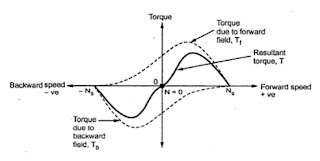
As the stator winding is fed from a single-phase supply, the flux in the air gap is alternating only, not a synchronously rotating one produced by a poly-phase (maybe two- or three-) winding in the stator of IM. This type of alternating field cannot produce a torque if the rotor is stationary (ω r = 0.0 ). So, a single-phase IM is not self-starting, unlike a three-phase one. However, as shown later, if the rotor is initially given some torque in either direction (ω r ≠ 0.0 ), then immediately a torque is produced in the motor. The motor then accelerates to its final speed, which is lower than its synchronous speed.

Single phase Induction Motor

Double Field Revolving Theory :

It explains the not self-starting nature of 1 phase IM. When the stator winding (distributed one as stated earlier) carries a sinusoidal current (being fed from a single-phase supply), a sinusoidal space distributed mmf, whose peak or maximum value pulsates (alternates) with time, is produced in the air gap. This sinusoidally varying flux (φ ) is the sum of two rotating fluxes or fields, the magnitude of which is equal to half the value of the alternating flux (φ/2), and both the fluxes rotating synchronously at speed, (Ns) in opposite directions. The flux or field rotating at synchronous speed, say, in the anticlockwise direction, i.e. the same direction, as that of the motor (rotor) taken as positive induces emf (voltage) in the rotor conductors. The rotor is a squirrel cage with bars short-circuited via end rings. The current flow in the rotor conductors and the electromagnetic torque are produced in the same direction as given above, which is termed assistive (+ve). The other part of the flux or field rotates at the same speed in the opposite (clockwise) direction, taken as negative. So, the torque produced by this field is negative (-ve), as it is in the clockwise direction, the same as that of the direction of rotation of this field. Two torques are in the opposite direction, and the resultant (total) torque is the difference between the two torques produced.
Speed-Torque characteristics of Single phase Induction Motor

If the forward slip is "s" then the backward slip is given by "2-s".At starting
Forward torque Tf=Backward torque Tb
Therefore fails to start but if we provide some initial torque in any direction, the motor starts to rotate in that direction.

Circuit Diagram :

Circuit Diagram of Single phase Induction Motor

Starting Methods:

The single-phase IM has no starting torque but has resultant torque, when it rotates at any other speed, except synchronous speed. It is also known that in a balanced two-phase IM having two windings, each having an equal number of turns and placed at a space angle of 90 degrees (electrical), and are fed from a balanced two-phase supply, with two voltages equal in magnitude, at an angle of 90 degrees, the rotating magnetic fields are produced, as in a three-phase IM.  So, in a single-phase IM, if an auxiliary winding is introduced in the stator, in addition to the main winding, but placed at a space angle of 90 degrees (electrical), starting torque is produced.

Resistance Split Phase Induction Motor :

Auxiliary winding with high resistance in series is to be added along with the main winding in the stator. This winding has a higher resistance to reactance (Ra/Xa) ratio as compared to that in the main winding and is placed at a space angle of 90 degrees from the main winding. The current (Ia) in the auxiliary winding lags the voltage (V) by an angle, φ a, which is small, whereas the current (Im) in the main winding lags the voltage (V) by an angle, φ m, which is nearly 90 degree. The phase angle between the two currents is (90° −φ a), which should be at least. This results in a small amount of starting torque. The switch, S (centrifugal switch) is in series with the auxiliary winding. It automatically cuts out the auxiliary or starting winding, when the motor attains a speed close to full load speed. The motor has a starting torque of 100−200% of full load torque, with the starting current as 5-7 times the full load current. The changeover occurs when the auxiliary winding is switched off.
Resistance Split Phase Induction Motor


Capacitor Start Induction Motor:

A capacitor along with a centrifugal switch is connected in series with the auxiliary winding, which is being used here as a starting winding. The capacitor may be rated only for intermittent duty, the cost of which decreases, as it is used only at the time of starting. This motor is used in applications, such as compressors, conveyors, machine tool drives, refrigeration, and air-conditioning equipment, etc.

Capacitor Start Induction Motor

Capacitor start Capacitor Run Induction Motor:

Two capacitors Cs for starting, and Cr for running, are used. The first capacitor is rated for intermittent duty, being used only for starting. A centrifugal switch is also needed here. The second one is to be rated for continuous duty, as it is used for running. The phase difference between the two currents is (φa+φm>90°) in the first case (starting), while it is 90 degrees for the second case (running). In the second case, the motor is a balanced two-phase one, the two windings having the same number of turns and other conditions are also satisfied. So, only the forward rotating field is present, and no backward rotating field exists. The efficiency of the motor under this condition is higher. Hence, using two capacitors, the performance of the motor improves both at the time of starting and then running. This motor is used in applications, such as compressors, refrigerators, etc.

Capacitor start Capacitor Run Induction Motor
Torque-Speed Characteristics of a Capacitor start Capacitor Run Induction Motor
Torque-Speed Characteristics of a C.S.C.R. IM

Shaded Pole Induction Motor:

This is a single-phase induction motor, with main winding in the stator. A small portion of each pole is covered with a short-circuited, single-turn copper coil called the shading coil. The sinusoidally varying flux created by ac (single-phase) excitation of the main winding induces emf in the shading coil. As a result, induced currents flow in the shading coil producing their own flux in the shaded portion of the pole. the net flux in the shaded portion of the pole (φ sp ) lags the flux (φ m′) in the unshaded portion of the pole resulting in a net torque, which causes the rotor to rotate from the unshaded to the shaded portion of the pole. The motor thus has a definite direction of rotation, which cannot be reversed. The reversal of the direction of rotation, where desired, can be achieved by providing two shading coils, one on each end of every pole, and by open-circuiting one set of shading coils and by short-circuiting the other set. The fact that the shaded-pole motor is a single-winding (no auxiliary winding) self-starting one, makes it less costly and results in rugged construction. The motor has low efficiency and is usually available in the range of 1/300 to 1/20 kW. It is used for domestic fans, record players and tape recorders, humidifiers, slide projectors, small business machines, etc. The shaded-pole principle is used in starting electric clocks and other single-phase synchronous timing motors.
Shaded Pole Induction Motor
Shaded Pole Induction Motor- Phasor Diagram