What is an Autotransformer?
The primary and secondary windings of a two-winding transformer have
induced emf in them due to a common mutual flux and hence are in phase. The currents
drawn by these two windings are out of phase by 180º. This prompted the use of a part
of the primary as secondary. This is equivalent to fusing the secondary turns into primary
turns.
 |
| Autotransformer - Physical Arrangement |
The fused section needs to have a cross-sectional area of the conductor to carry (I₂−I₁)
Ampere. This ingenious thought led to the invention of an autotransformer.
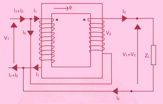 |
| Two Winding Transformer used as an autotransformer |
If we are not looking at the savings in the material, even then going in for the autotransformer type of connection can be used with the advantage, to obtain a higher output. A regular two-winding transformer of a voltage
ratio V₁: V₂, the volt-ampere rating being V₁I₁ = V₂I₂ = S. If now the primary is connected
across a supply of V₁ volt and the secondary is connected in series addition manner with the
primary winding, the output voltage becomes (V₁ + V₂) volt. Thus an increased rating can be obtained compared to a two-winding transformer
with the same material content. The windings can be connected in a series opposition fashion
also.
Equivalent Circuit of an Autotransformer:

 |
| Equivalent Circuit of autotransformers |
The
above equivalent circuit can now be compared with the approximate equivalent circuit of
a two-winding case Re = r₁ + a²r₂ and Xe = xl₁ + a²xl₂. Thus in the case of an autotransformer total value of the short circuit impedance is lower and so also the percentage
resistance and reactance. Thus the full load regulation is lower. Having a smaller value
of short circuit impedance is sometimes considered to be a disadvantage. That is because the short circuit currents become very large in those cases. The efficiency is higher in autotransformers compared to their two winding counterparts at the same load. The phasor
diagram of the operation for the autotransformer drawing a load current at a lagging power
factor angle of θ₂ is shown in Figure given below
 |
| Phasor Diagram of Operation of an autotransformer |
Advantages:
There are several advantages to going in for the
autotransformer type of arrangement.
- The voltage/current transformation and impedance conversion aspects of a two-winding transformer are retained but with lesser material (and hence lesser weight) used.
- The losses are reduced increasing efficiency.
- Reactance is reduced resulting in better regulation characteristics. All these benefits are enhanced as the voltage ratio approaches unity.