Constructional Features:
Transformers used in practice are of extremely large variety depending upon the
end use. In addition to the transformers used in power systems, power transmission, and
distribution, a large number of special transformers are in use in applications like electronic
supplies, rectification, furnaces, traction, etc. The principle of operation of these transformers also is the same but the user requirements
differ. Power transformers of smaller sizes could be air-cooled while the larger ones are
oil cooled. These machines are highly material-intensive types of equipment and are designed to
match the applications for the best-operating conditions. Hence they are ‘tailor-made’ to a
job. This brings in a very large variety of their constructional features.
Constructional Aspects:
These can be broadly divided into:
- Core Construction
- Winding arrangements
- Cooling aspects
Core Construction:
The transformer core for the power frequency application is made of highly permeable
material. The high value of permeability helps to give a low reluctance for the path of
the flux and the flux lines mostly confine themselves to the iron. Relative permeability µr
well over 1000 is achieved by the present-day materials. Silicon steel in the form of thin
laminations is used as the core material. Over the years progressively better magnetic properties
are obtained by going in for Hot rolled non-oriented to Hot rolled grain-oriented steel. Later better laminations in the form of cold Rolled Grain Oriented (CRGO), -High B (HiB)
grades became available. The thickness of the laminations progressively got reduced from
over 0.5mm to the present 0.25mm per lamination. These laminations are coated with a thin
layer of insulating varnish, oxide, or phosphate. The magnetic material is required to have
a high permeability µ and a high saturation flux density, a very low remanence Br and a
small area under the B-H loop to permit a high flux density of operation with low magnetizing
current and low hysteresis loss.
 |
| Core and Shell Type Construction |
Windings:
Windings form another important part of transformers. In a two-winding transformer, two windings would be present. The one which is connected to a voltage source and
creates the flux is called a primary winding. The second winding where the voltage is
induced by induction is called a secondary. If the secondary voltage is less than that of the
primary the transformer is called a step-down transformer. If the secondary voltage is more
then it is a step-up transformer. A step-down transformer can be made a step-up transformer
by making the low voltage winding its primary. Hence it may be more appropriate to designate
the windings as High Voltage (HV) and Low Voltage (LV) windings. The winding with
more turns will be an HV winding. The current on the HV side will be lower as the V-I product is constant and given as the VA rating of the machines. Also, the HV winding
needs to be insulated more to withstand the higher voltage across it. HV also needs more
clearance to the core, yoke, or body. These aspects influence the type of winding
used for the HV or LV windings.
 |
| Concentric and Sandwich Coils |
Transformer Cooling:
Scaling advantages make the design of larger and larger unit sizes of transformers
economically attractive. Consider a transformer of a certain
rating designed with a certain flux density and current density. If now the linear dimensions
are made larger by a factor of K keeping the current and flux densities the same the core and
conductor areas increase by a factor of K². The losses in the machine, which are proportional
to the volume of the materials used, increase by a factor of K³. The rating of the machine
increases by a factor of K⁴. The surface area however increases by a factor of K² only. Thus the ratio of loss per
surface area goes on increasing by a factor of K. The substantial increase in the output is
the major attraction in going in for larger units. However, cooling the transformer becomes
more and more difficult. As the rating increases better cooling techniques are needed.
Simple air cooling of the transformers is adopted in dry-type transformers. The limit
for this is reached by the time the rating is a few kVA. Hence air cooling is used in low-voltage machines. This method of cooling is termed AN(Air Natural). Air Blast(AB)
method improves on the above by directing the blast of air at the core and windings. This
permits some improvement in the unit sizes.
Substantial improvement is obtained when the transformer is immersed in an oil tank.
The oil reaches the conductor surface and extracts the heat and transports the same to the
surface of the tank by convection. This is termed the ON (Oil Natural) type of cooling. This
method permits the increase in the surface available for cooling further by the use of
ducts, radiators, etc.
OB(Oil Blast) method is an improvement over the ON type and it directs a blast of air on the cooling surface. In the above two cases, the flow of oil is by natural convective
forces. The rate of circulation of oil can be increased with the help of a pump, with the
cooling at the surface remaining natural cooling to air. This is termed OFN (Oil Forced
Natural). If now a forced blast of air is also employed, the cooling method becomes OFB(
Oil Forced Blast). Forced circulation of oil through a radiator is done with a blast of air over the radiator surface. A substantial amount of heat can be removed by employing water
cooling. Here the hot oil going into the radiator is cooled by a water circuit. Due to the
high specific heat of water, heat can be evacuated effectively. Next in the hierarchy comes OFW
which is similar to OFB except that instead of a blast of air a forced circulation of cool water
in the radiator is used in this.
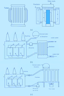 |
| Power Transformer Cooling |